
‘Unlocking the potential for innovation requires a space that can adapt and evolve.’
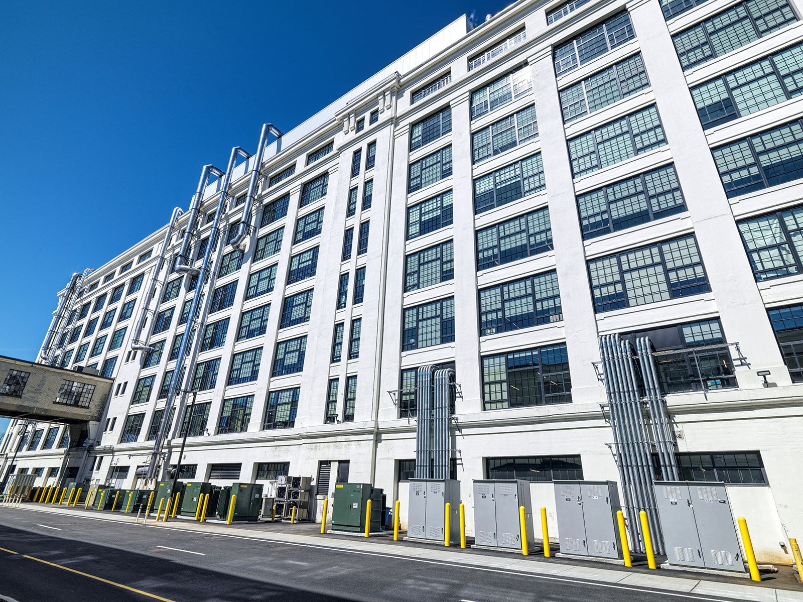
The captivating history of the Innovation and Design Building (IDB) in Boston, MA, is abundant and rich. Originally constructed in the 1910s, the building served as a massive Army storehouse for the Commonwealth of Massachusetts. It also played a crucial role in supporting the city’s thriving maritime industry, housing warehouses, and providing storage space for a wide range of goods.
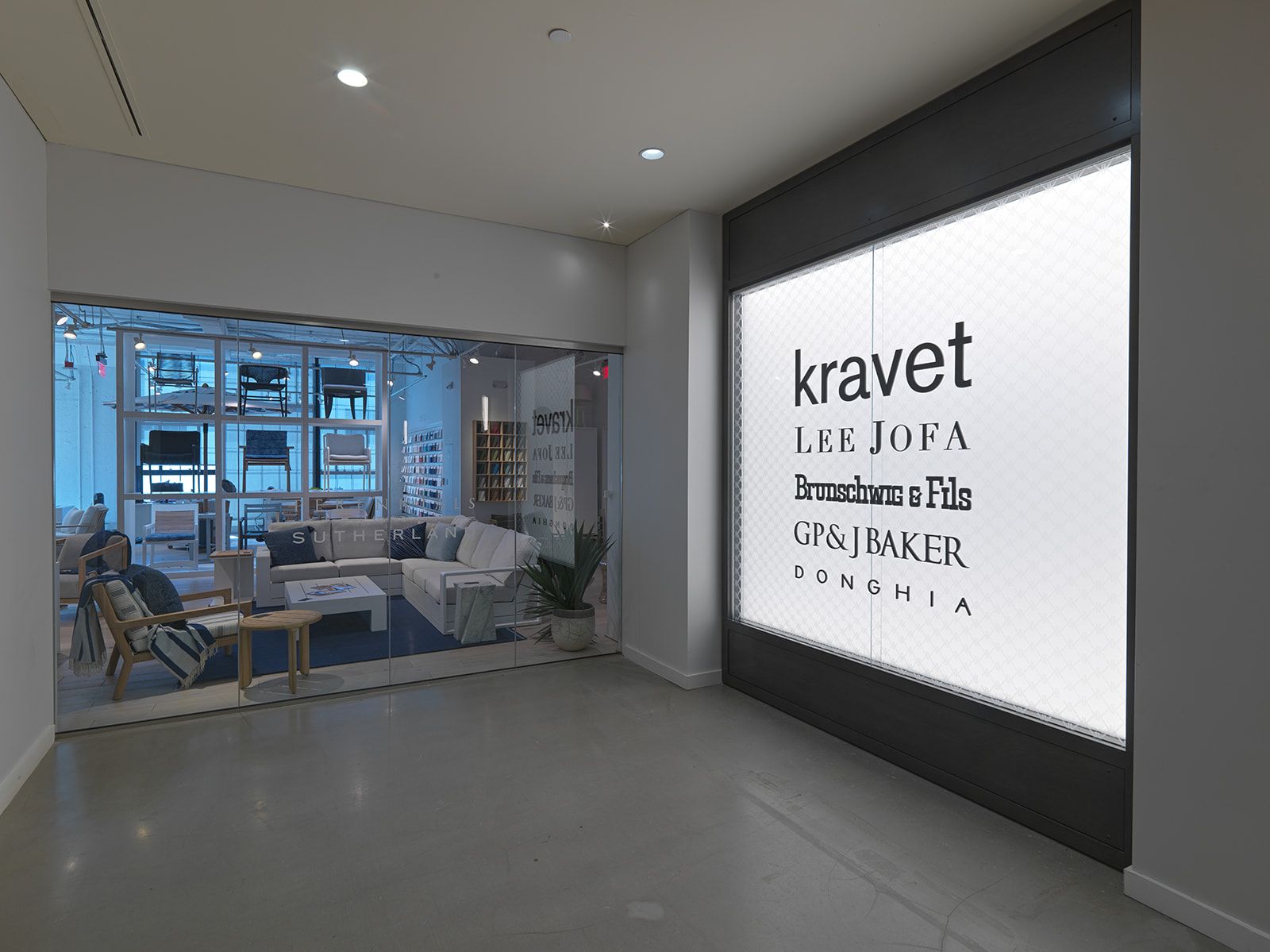
Over time, the IDB underwent significant transformations, reflecting the evolving needs of the City and its industries. In the mid-20th century, the building became a hub for design, transitioning into a prominent location for interior design showrooms and studios. It has served as a creative haven, attracting designers, architects, and artists who are shaping the visual landscape of Boston.
In recent years, the IDB has continued to reinvent itself, embracing new possibilities and expanding its repertoire. Recognizing its potential as a vibrant ecosystem for adaptability and collaboration, the latest chapter in the IDB’s history marks a monumental shift as it steps into the realm of scientific exploration.
In response to the City’s growing need for laboratory space, owners Jamestown and Related Beal initiated an extensive lab conversion across four floors in IDB’s One Design Center Place, as well as a comprehensive overhaul of the roof. Construction, led by Wise, and design, led by BR+A Engineers and SGA Architects, have been completed with the conversion officially offering the IDB its next opportunity to innovate Boston.
Below are just a few of the impressive pieces of scope that Wise, project partners, and trade partners took on together as a team:
Occupied Building: Preserving Functionality Amidst Transformation
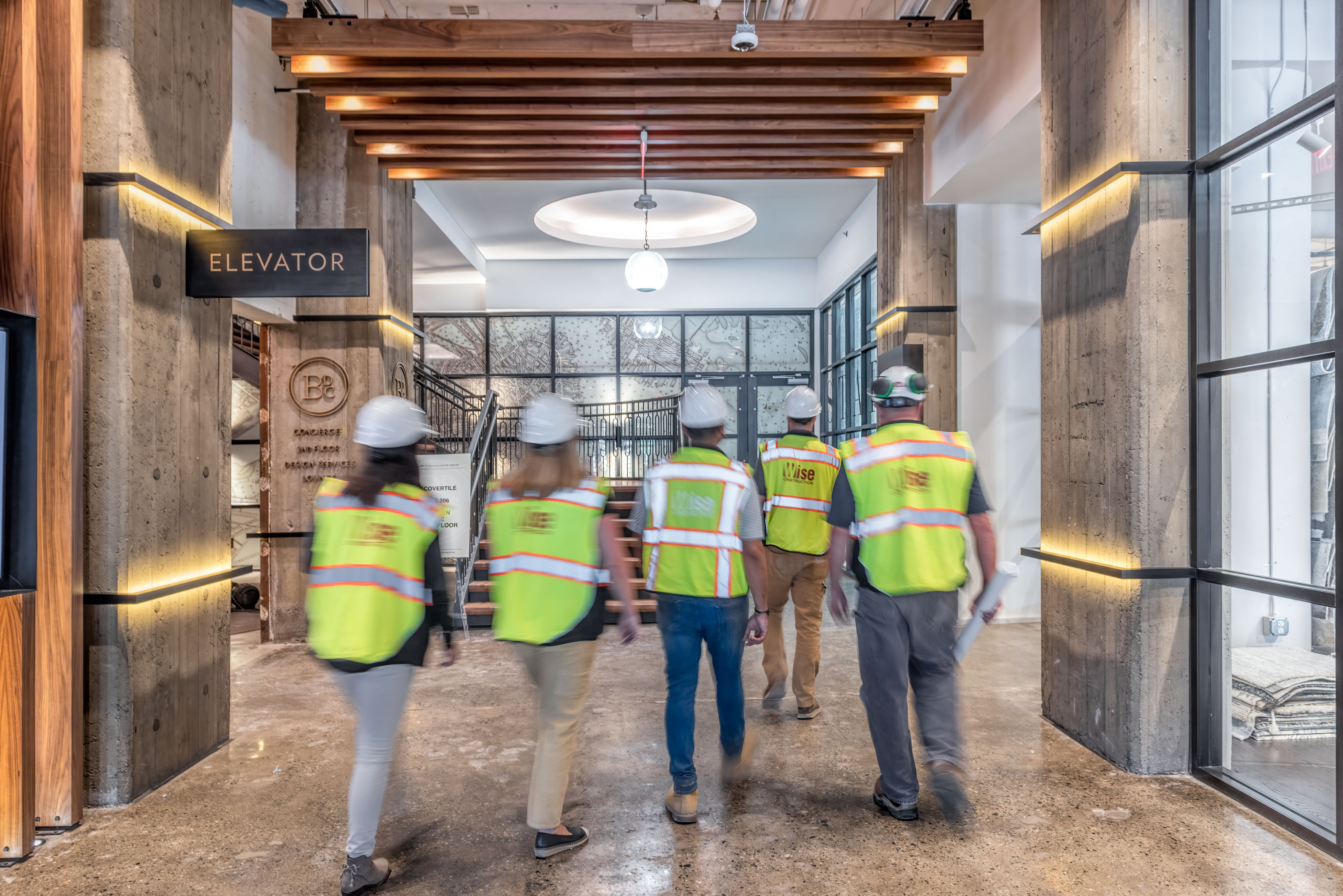
A standout achievement of this project was our ability to seamlessly work around 35 tenants occupying our construction area. The project’s ambitious scope necessitated meticulous coordination to minimize disruptions and ensure the smooth functioning of existing tenants. Our project primarily focused on the roof and vacated floors 4-8 on the western side of IDB in One Design Center Place. However, to meet the project’s design needs, a lot of that work was carried through to the occupied spaces on floors 1-3.
Throughout the construction process, the Wise team prioritized transparent communication with tenants, holding weekly meetings to provide updates on the project’s status and to collaborate on minimizing disruptions to their daily operations. In one notable instance, a tenant needed to remain active 24/7 as they served as the main headquarters for distribution to other locations. To support their continuous operations, we implemented temporary systems that maintained heat, cooling, and water during critical shutdowns. We extended support to the rest of the building for mandatory shutdowns, coordinating and designing other temporary systems including a chiller, RTUs and exterior duct.
Effective noise management was a significant undertaking during construction. To avoid disturbances, noisy work was restricted to the hours before 8:00 am. Demolition was carried out at night or specified hours, and any work in occupied spaces was carried out in the early morning between 3:00 am and 8:00 am. This allowed the team to ensure progress while minimizing disruptions to the building’s occupants.
One of the major construction challenges involved installing a massive 19ft by 9ft duct shaft that extended from the roof down to the fourth floor. Precise coordination was required to relocate all mechanical, electrical, and plumbing elements. Temporary systems were employed to ensure continuous access to essential utilities for tenants below throughout the process. The addition of a freight elevator shaft running from the roof to every floor of the building also presented its own set of complexities, requiring thorough planning and coordination.
Minimal disruptions hinged on tenant coordination, transparent communication, and the collective expertise of our skilled team of partners. The unwavering commitment to maintaining building operations ensured the project’s overall success.
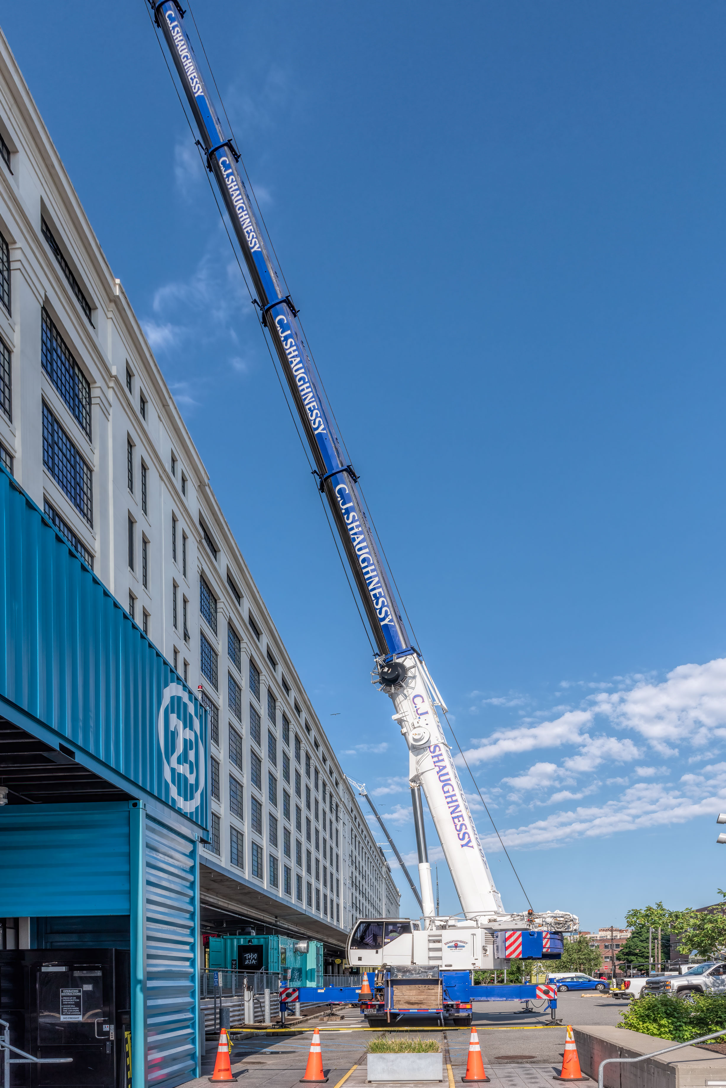
Crane Pick Scope: Lifting Coordination to New Heights
The crane pick scope for this project encapsulated an impressive array of coordinated efforts and intricate maneuvers. With a total of 220 crane plans submitted, spanning over 300 crane days and involving 6,000 individual crane picks, this phase of the construction showcased a remarkable synergy of planning, coordination, and execution.
These picks encompassed a diverse range of components, including heavy mechanical and structural elements, piping, ductwork, equipment, and other miscellaneous pieces. The process involved a careful dance of scheduling and coordination, especially during instances where multiple cranes operated concurrently. At times, five cranes would be working in tandem, each contributing to the intricate dunnage puzzle being assembled on the roof.
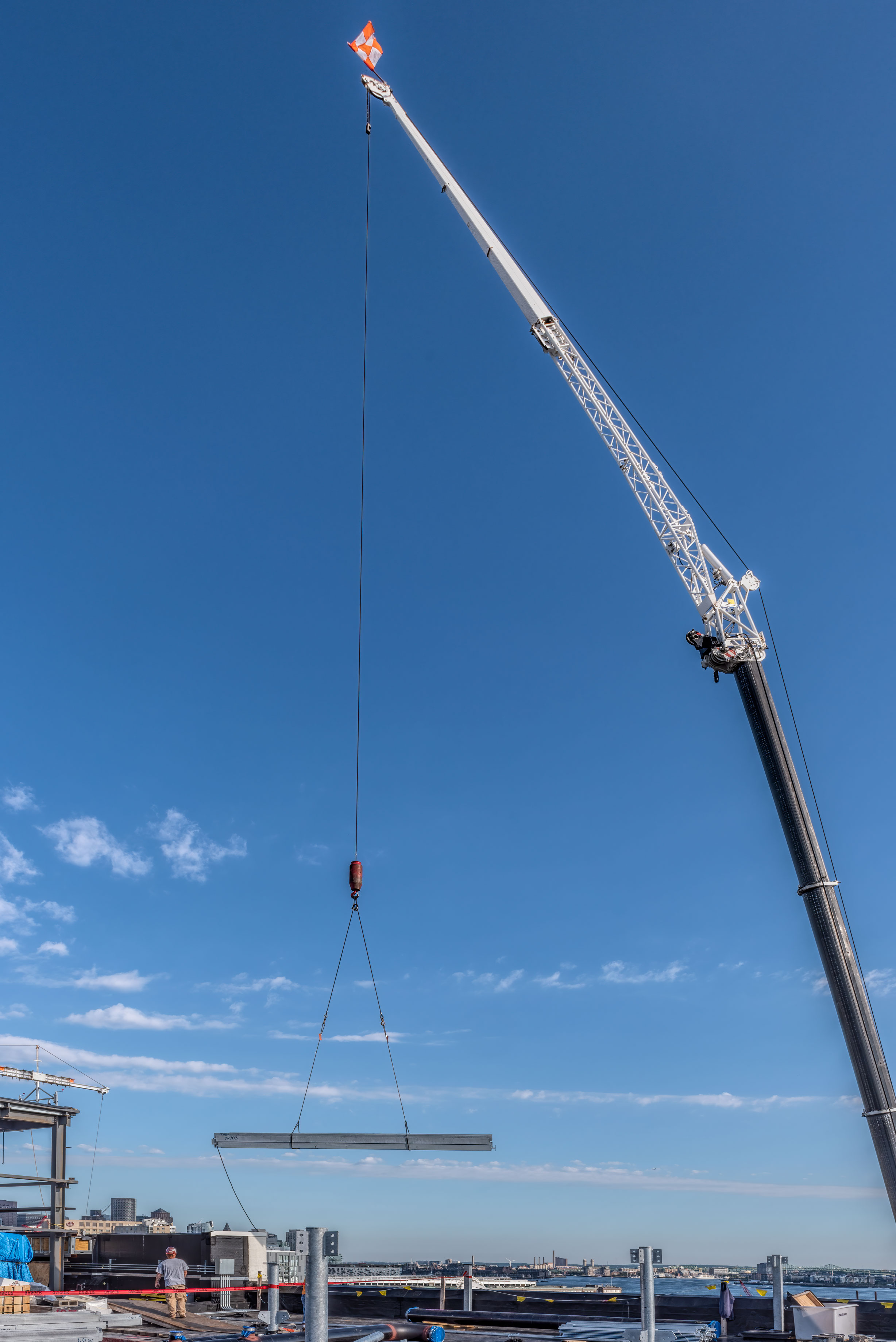
Among the notable crane picks was the assembly and placement of Wise’s biggest pick-to-date—a 70,000lb, 365 SF generator. The generator was assembled and shipped from Texas to Boston, and on a particularly windy day, this large piece of critical machinery was safely and successfully picked onto the roof. The subsequent month saw the team thoroughly configuring the equipment, setting the stage for its pivotal role in delivering a 2000KW output, designed to serve as standby power for the floors where Wise was actively engaged.
The crane pick scope also embraced adaptability, as it accommodated the busy schedule of the nearby cruise ship port. This consideration resulted in 78 days of port activity and 53 dedicated workdays that avoided crane operations on the main loading dock street. The entire endeavor was meticulously guided by a comprehensive three-week look-ahead, allowing for harmonious progression.
In summary, the crane pick scope of this project was a remarkable display of precision, coordination, and resilience. It showcased the successful orchestration of hundreds of crane plans, thousands of lifts, and multiple cranes working in concert, all while accommodating external constraints.
Infrastructure: Steel Support Ensuring Building Safety and Application
The infrastructure scope included extensive collaboration and coordination with the engineer to ensure safety and proper placement of the equipment. Due to the weight of the equipment, assistance from a specialist and significant alterations were required before any equipment was positioned and set on the roof to prepare for the future laboratory tenants.
Working closely with the specialist, we calculated and strategically determined the best spots on the roof to distribute the weight, considering the existing concrete columns on the floors below. It was imperative to disperse the weight of the equipment around the roof for the structural safety of the whole building. The steel dunnage and equipment locations were carefully chosen to rely on the building’s infrastructure for support. To reinforce the dunnage and create a level surface, we cut out a 30ft-by-30ft section of the roof and laid out steel sheets to accommodate the addition of new equipment.
Once all the necessary inspections and approvals were obtained, we began assembling the steel dunnage, piece by piece. After successful assembly of the steel dunnage, we could safely install the AHUs and other equipment. Then we ensured the surrounding areas were equipped with railings, stairs, and platforms for convenience and safety. Simultaneously, we meticulously planned and coordinated the duct work and piping to accommodate the weight distribution and required placement of the equipment on the roof.
The amount of steel required to accomplish and structurally support all the necessary equipment included:
- Partitions
- 4,600 LF of framing
- 109,000 SF of gypsum wallboard
- Shafts
- 2,500 LF of framing
- 34,000 SF of shaft wall liner
- 335 tons of steel
- 130 new stub columns for roof dunnage
- 350 cubic yards of concrete placed = 35 concrete trucks
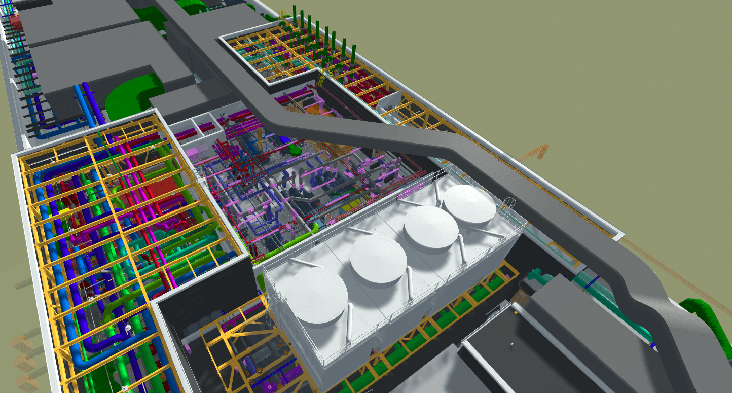
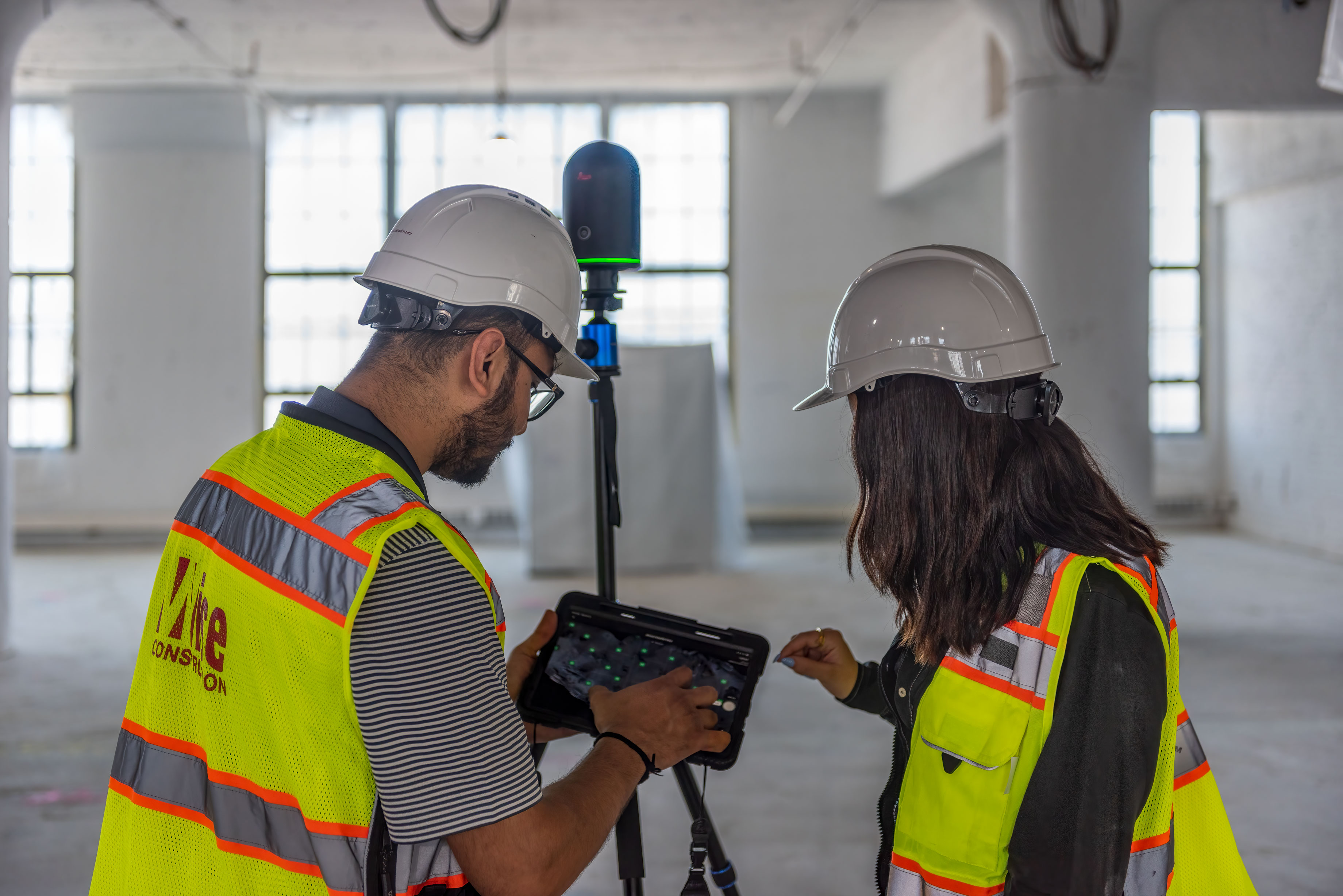
BIM/VDC: Facilitated Prefabrication Plan
The innovation and assembly of the project began with the integration of Building Information Modeling (BIM) and Virtual Design and Construction (VDC) technology. With scanning technology, we collaborated with the architect and engineer to create a master plan for prefabricating all the necessary components.
Utilizing OpenSpace we captured 3D models of all areas we needed to design and visualize for our prefabrication plan. The process started with creating 3D drawings of all the components of MEP work and architectural designs on the roof and within the building. Through 3D drawing, the MEP equipment was carefully crafted to ensure a perfect fit. We were able to visualize all the components that would fit within the roof, penthouse, elevator shaft, and interior risers through each floor of the building before the physical assembly commenced. With this technique the project’s efficiency significantly improved, as clashes were detected early on and coordination between building tenants and trade partners was well managed.
With the prefabrication completed and all components delivered, it was time to put all the puzzle pieces together. This operation involved the installation of steel work, mechanical pipe, duct work, risers, and Air Handler Units. Thanks to this technology, we navigated around the building’s existing conditions and occupied spaces with ease and utmost consideration for any occupied space.
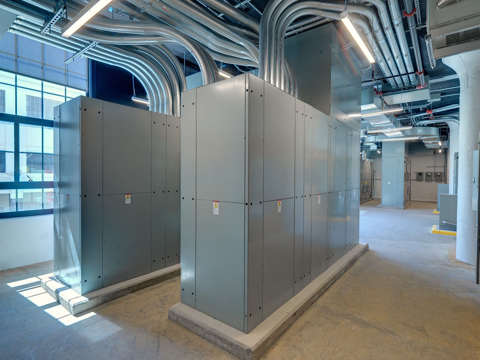
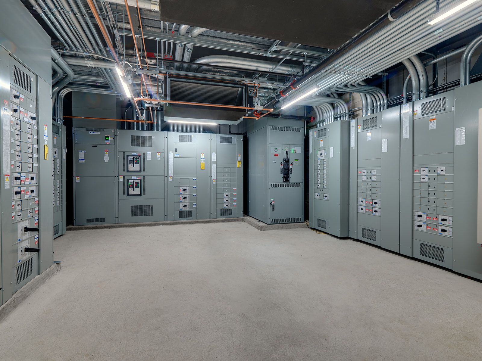
Electrical Scope: Power Enhancement for Innovation Building
The electrical scope involved extensive upgrades and expansions to enhance the power supply for both new equipment and existing tenant areas. Working hand-in-hand with Lighthouse Electrical, a dedicated electrical room was added to the constructed penthouse, facilitating efficient power distribution to all the new rooftop equipment. The second floor housed the main electrical distribution for One Design Center Place, which incorporated four new switch gears to cater to multiple tenant floors and rooftop equipment.
To ensure uninterrupted power supply, we installed a massive 70,000 LB generator on the roof, which is fueled by a substantial 10,000-gallon oil tank. The tank was securely positioned in an excavated section of the ground, supported by sheet piles. The distribution systems were equipped with oil pumps and floater alarms to ensure its smooth and reliable functioning.
We utilized and installed massive amounts of electrical conduit, wires, and equipment, as demonstrated by these statistics:
- Distribution 16,000’ of conduit (3 miles) and 65,000’ of wire (12 miles)
- Mechanical 20,000’ of conduit (3.5 miles) and 90,000’ of wire (17 miles)
- Installation of:
- Four – 2500KW 13.8V-480V transformers
- 7 switchboards
- 29 panels
- 14 transformers
- 2 – 140’ runs of TI bus risers
- One – 2,000KW standby generator
- 3 switchboards
- 14 panels
- 4 transformers
- 2 – 140’ runs of TI bus risers
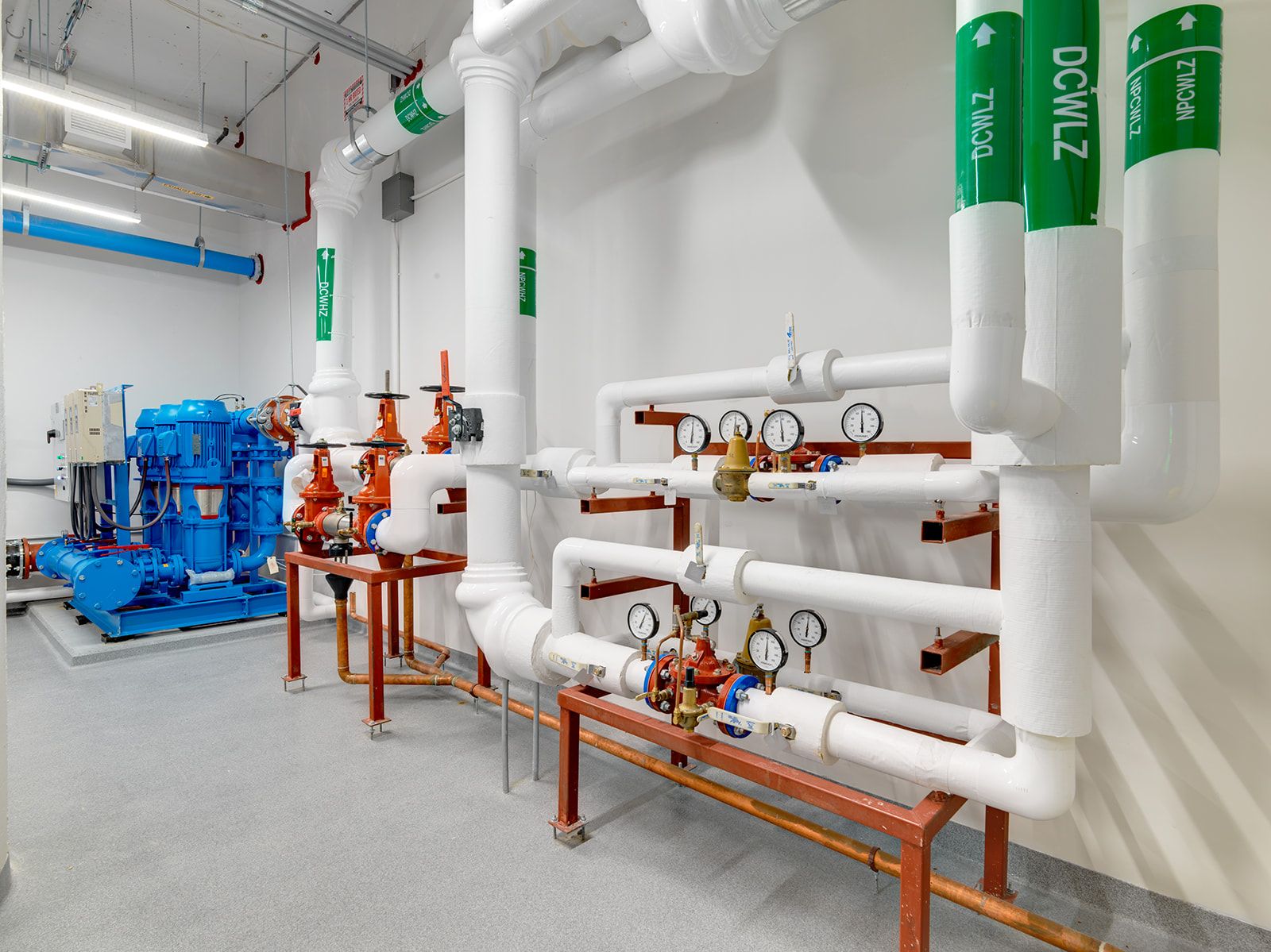
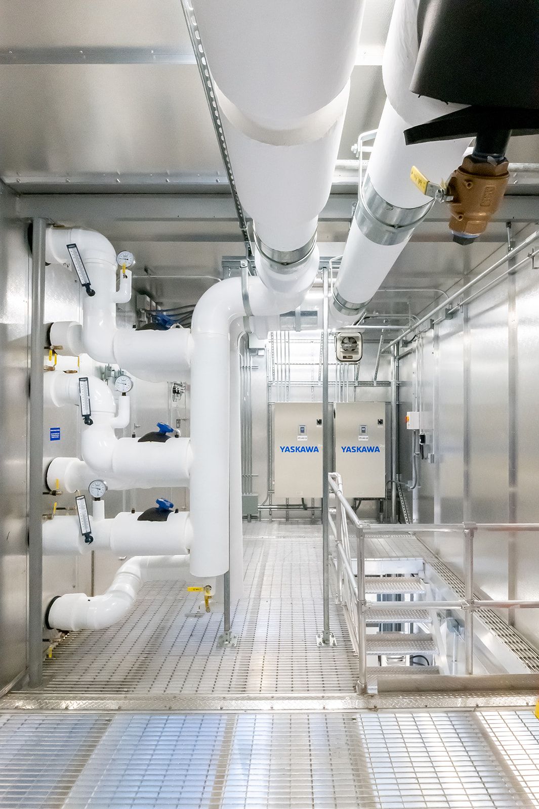
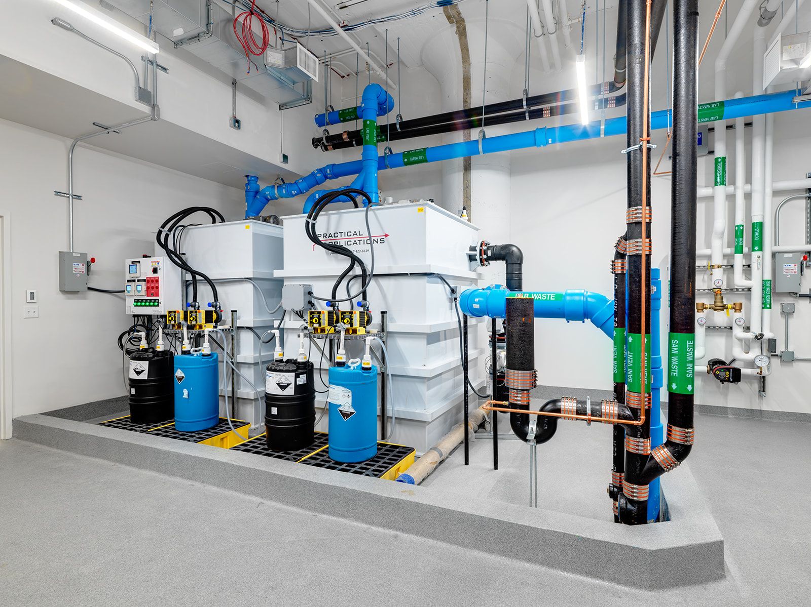
Plumbing Scope: Elevated Water System Ready for Laboratory
Comprehensive and complex plumbing systems were put into place to meet the intricate requirements of the future laboratory tenants on floors 4-8. Extensive modifications and additions were made throughout the building, including underground, on the first floor, penthouse, and rooftop. We constructed trenches for piping along with pH, chemical, and water distribution rooms for the intricate needs of the future tenants.
Due to the absence of a basement within the building, we began digging trenches and tunnels underground to house all the piping for the new pH and chemical rooms. We created a 4ft clearance and multiple access points for safety and the ease of multiple workers in the tunnels at once. Once all the pipping was installed, we carefully filled the area and reinforced every opening with structural components.
Then on the first floor we started with a chemical room, which is a dedicated storage space for essential laboratory necessities. Additionally, we revamped the pH room with laboratory waste neutralizers, plumbing systems, and tempered cold-water pumps. In between our work we provided temporary water systems that were in place 24/7 to ensure that occupied tenants were not affected by any plumbing shutdown.
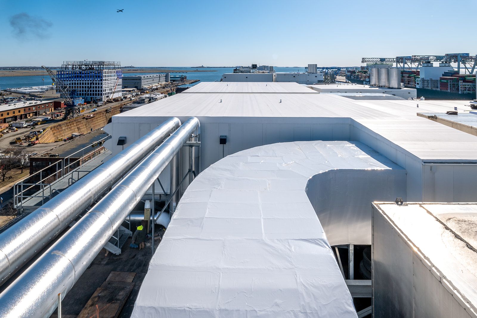
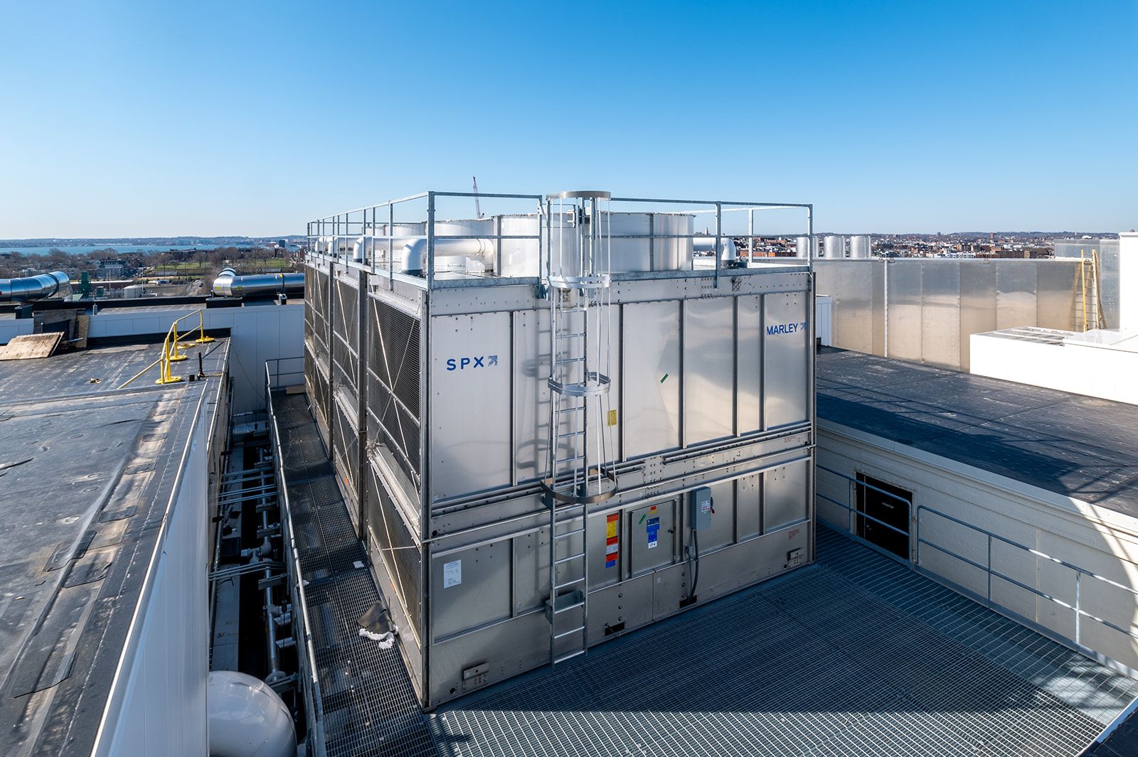
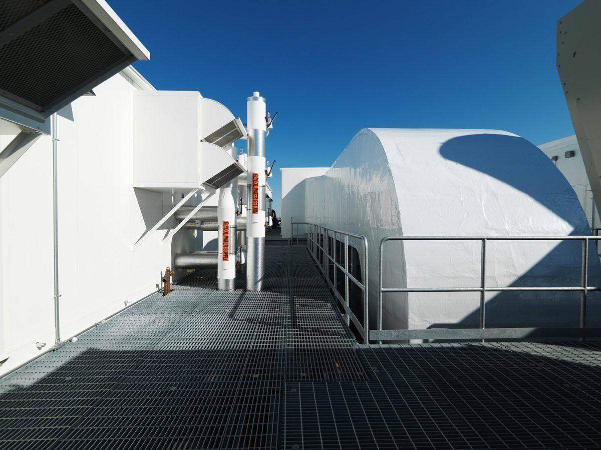
Moving up to the penthouse, we installed a sophisticated water distribution system, overseeing both hot and cold-water pumps. Further modifications occurred atop the roof where the 30ft-by-30ft steel leveling sheets provided support to the essential cooling water tower. This tower not only supplies essential chilled water to the future laboratories, but also conditions the circulating air.
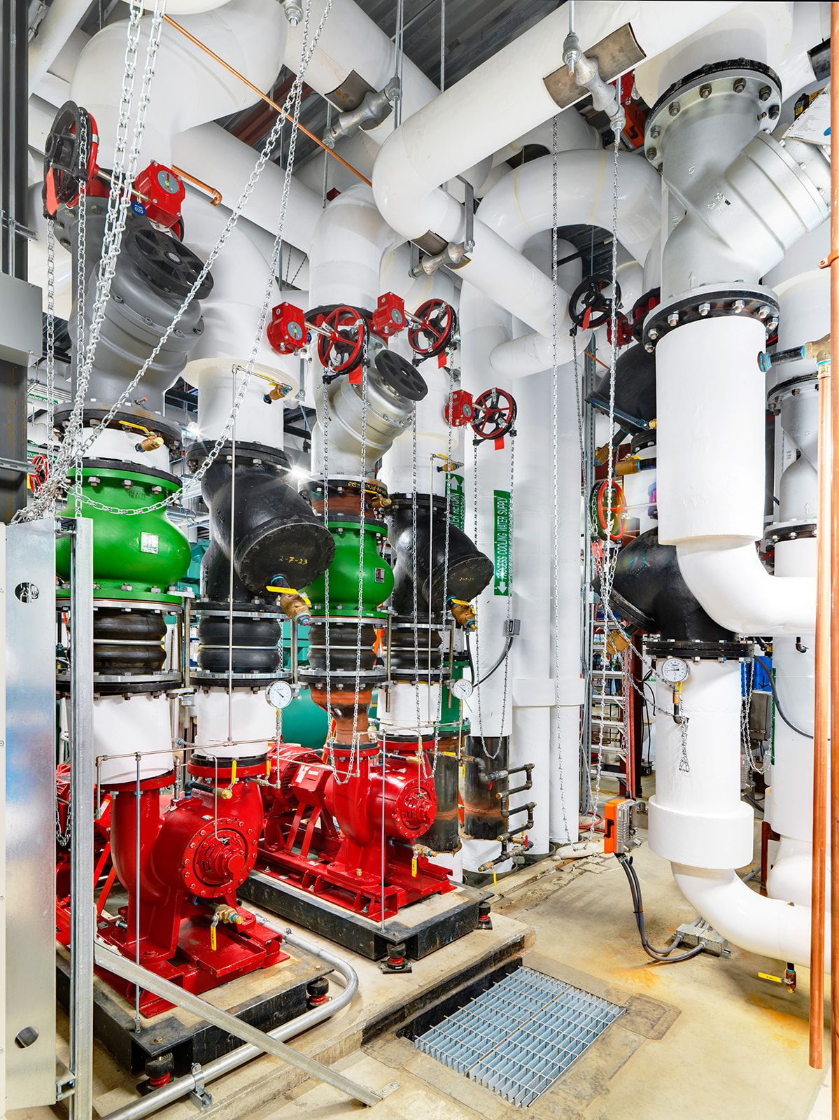
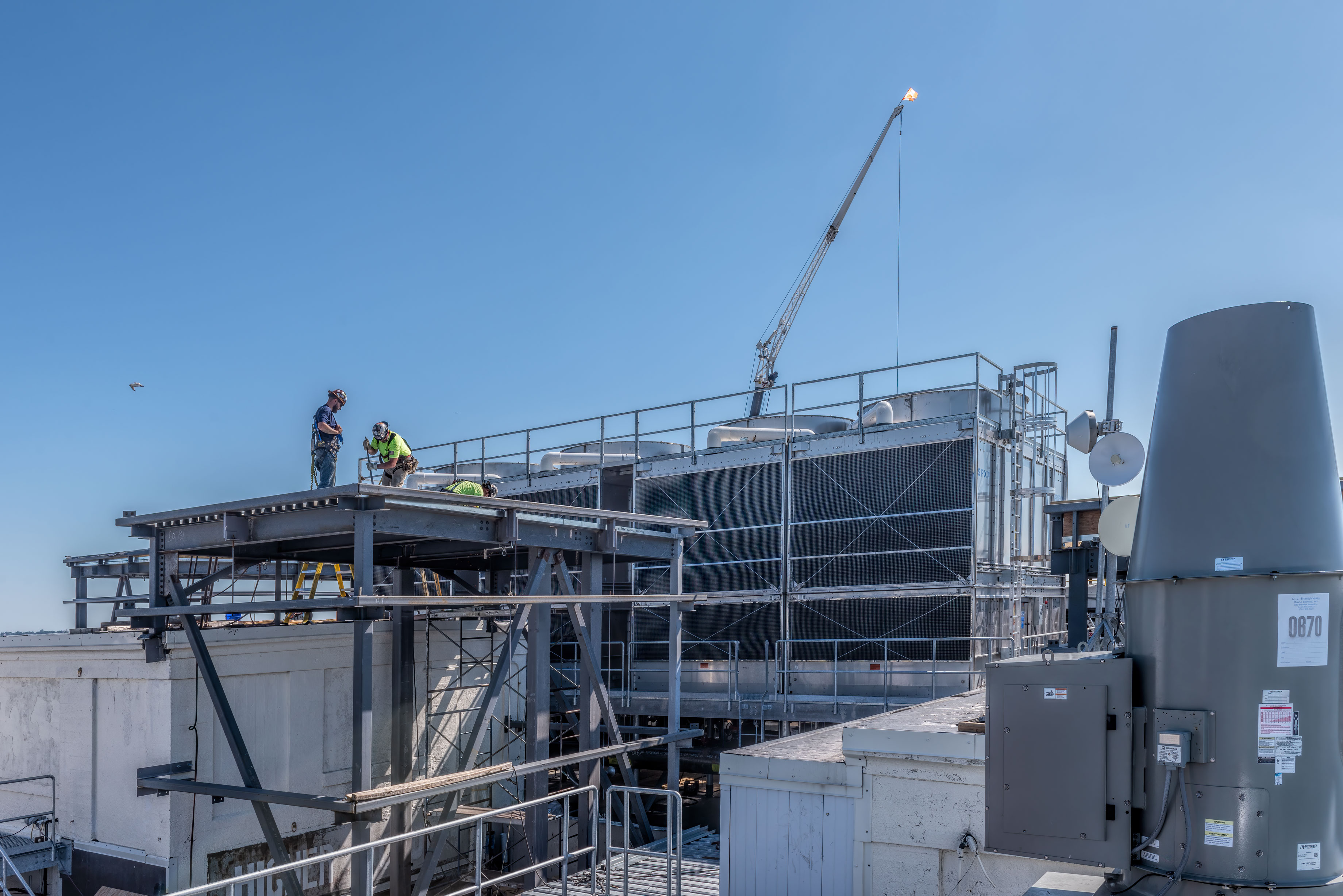
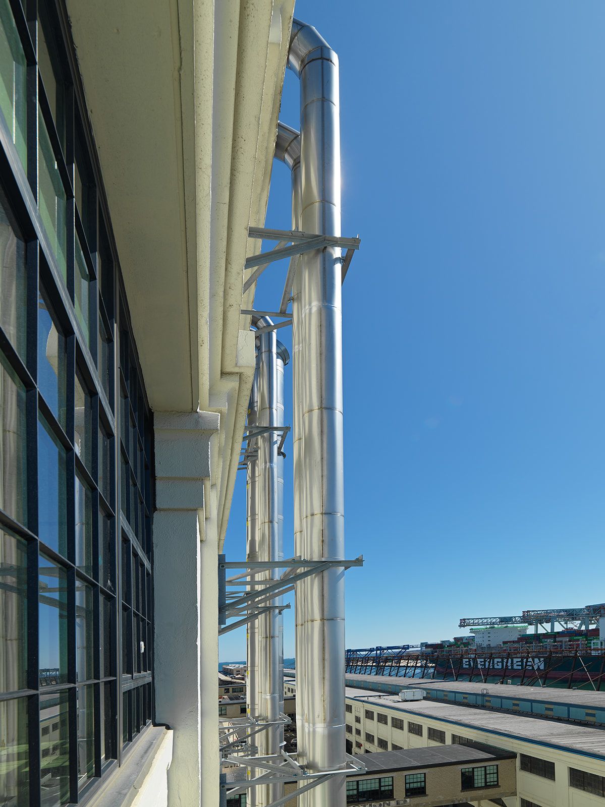
Mechanical/HVAC Scope: A Roof Fit for a Lab
Due to the inherently specialized nature of this project as a lab conversion, a significant portion of our efforts was devoted to equipping the roof with the necessary HVAC/Mechanical equipment to cater to the specific requirements of a laboratory.
Lab spaces have unique requirements for air quality, temperature, pressure, and safety that standard HVAC systems cannot adequately address. Specialized HVAC equipment is designed to meet these specific needs, establishing a controlled, secure, and efficient environment conducive to scientific research, experiments, and processes. Because of this, and the scope of the floors we were prepping, a substantial amount of equipment had to be transported onto the roof and through the building. This equipment included:
- 4 Cooling Towers
- 8 Air Handlers
- 4 Exhaust Air Handlers
- 6 Commercial Boilers
- 2 Commercial Chillers
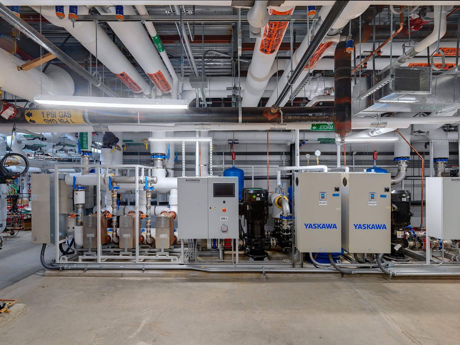
- 60+ VFDs
- 15 System Pumps
- 12 of the biggest duct risers to leave the fabrication facility
- 2 Energy Recovery Skids
Perhaps the most significant HVAC endeavor was the construction of a 19×9 foot shaft and duct extending from the roof to the fourth floor—the largest duct that Cox Engineering has ever manufactured. The initial steps involved orchestrating the removal of MEPs and installing the necessary steel to support the concrete before cutting openings for the duct through each floor. Subsequently, safety rails were positioned around each opening in preparation for the placement of the shaft. To put it simply, the large duct was essential to accommodate the substantial airflow requisite for the future laboratory tenant spaces. Extensive coordination with Cox and our various trade partners facilitated the seamless installation of the duct onto the roof and through each floor, supplied by two AHUs we situated on the roof shortly before.
Another important mechanical component of the project involved installing a new elevator shaft spanning from the first floor to the roof. Comparable to the process for the duct, relocating all MEPs was imperative, with the added complexity of navigating through three active tenant areas on floors 1-3. Paying close attention to these operational spaces, we dismantled the walls and eventually assembled steel and a wooden shaft traversing all floors. Once the components were in place, the elevator company proceeded to construct the rails and platform deck, then installed steel walls around the platform, and added doors and final finishes.
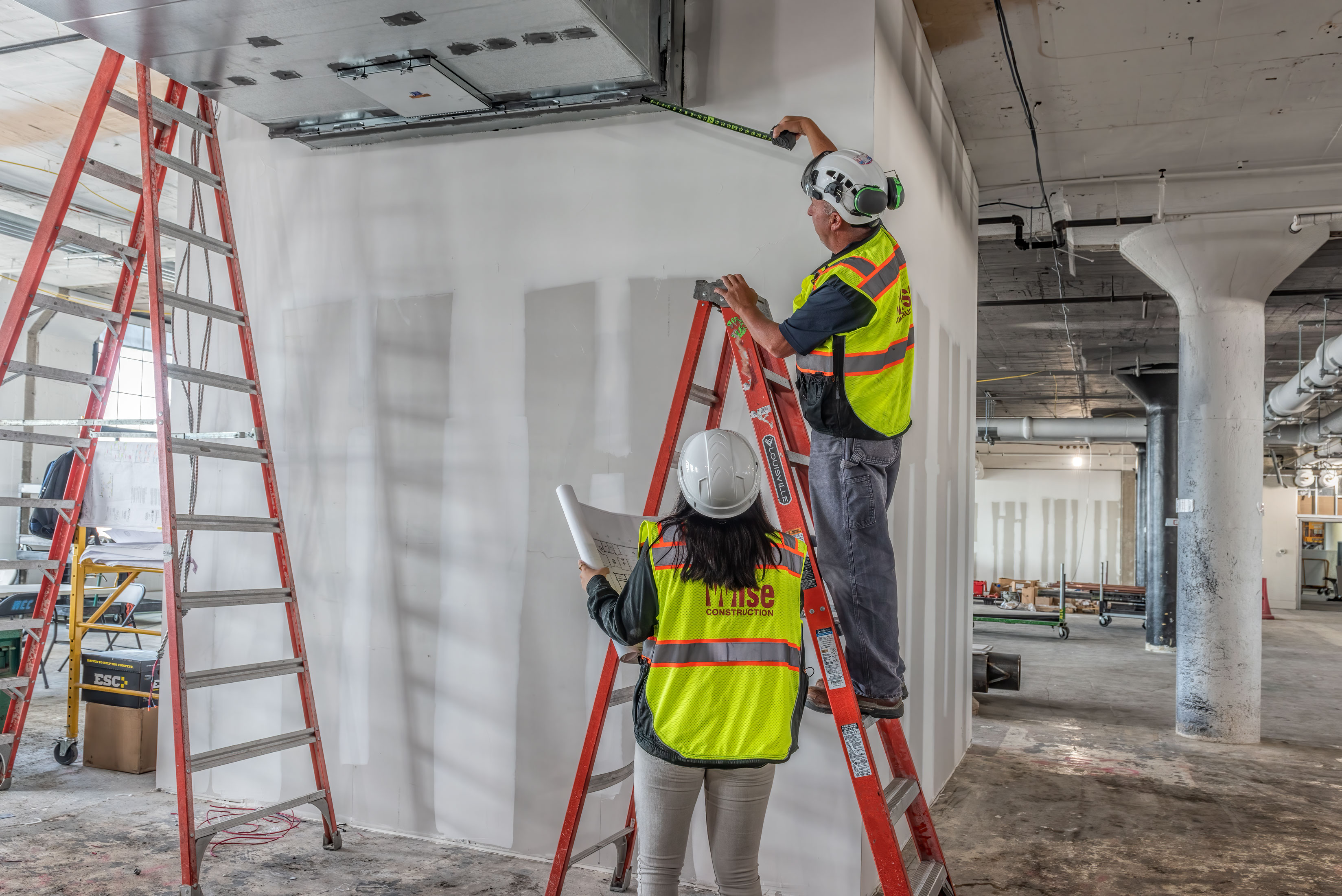
Interior Renovations (Floors 4-8): From Retail to Lab
With the completion of essential tasks such as establishing the mechanical, electrical, and plumbing frameworks, it is important for us to shift our attention back to the four prospective lab tenant floors, now primed for their future use. Initially, these floors had been outfitted for corporate and retail tenants, requiring an extensive demolition process.
Once the demo was complete, we began the installation of distribution piping interconnecting the floors, enabling the seamless transfer of essential resources to each of the floors from all the new equipment we placed onto the roof. Cooling and hot water risers were strategically integrated, ensuring the efficient distribution of utilities to each tenant.
We were fortunate enough to have two tenants, out of the four floors, who occupied a portion of the sixth and eighth floor. To mitigate disruption to these tenants, we devised a specialized logistics plan, featuring the installation of temporary partitions to isolate our ongoing construction activities.
_
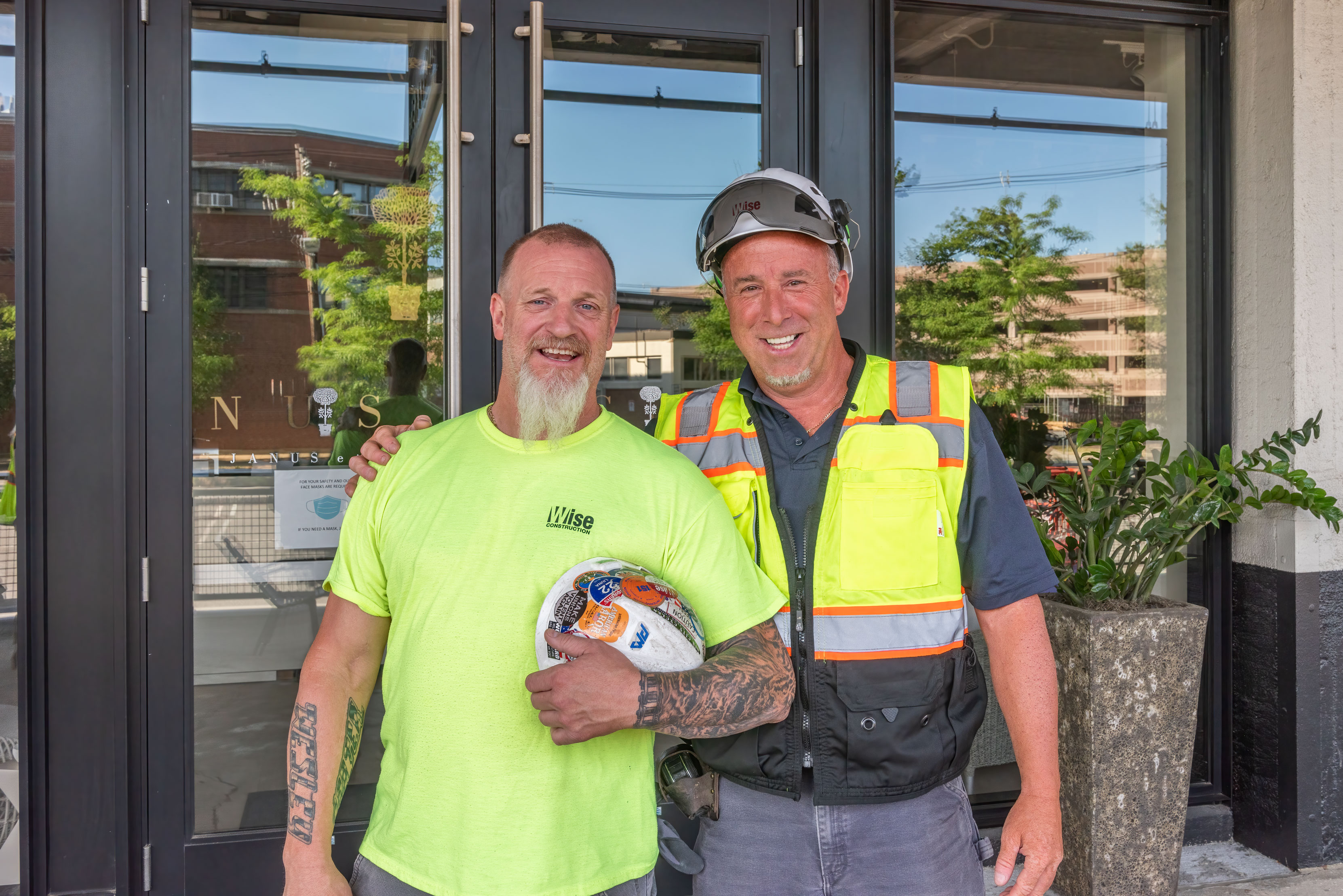
In closing, we stand in awe of the incredible journey this project has taken us on. It has not only been a team effort—it’s been a symphony of dedication, expertise, and sheer determination. To each individual who played a role, we extend a heartfelt ‘Wise Thank You’. We deeply acknowledge your passion and tireless commitment that fueled this project.
What we have both written and photographed tells a story that goes beyond a beautifully finished, lab-ready building. It encapsulates more than 26,000 hours of unwavering effort on and off-site, hundreds of thousands of transformed square footage, and an incessant collaborative effort between construction and design.
A picture is indeed worth a thousand words, but in our case, it symbolizes the culmination of 280,000 SF of renovated space and the extraordinary commitment of our team. We hope that this story serves as a reminder of the remarkable heights we have achieved together. Congratulations!
Thank You to our Project Partners:
Owners: Jamestown and Related Beal
Architect: SGA
MEPFP Engineer: BR+A Consulting Engineers
Structural Engineer: McNamara Salvia Structural Engineers
Civil Engineer: Howard Stein Hudson
Electrical: Lighthouse Electrical Contracting
Fire Protection Subcontractor: American Plumbing & Heating
Fire Alarm Subcontractor: Sullivan & McLaughlin
HVAC (Subcontractor or Engineer): Cox Engineering
Plumbing Subcontractor: P.J. Dionne Company inc.
Demolition: Select Demo Services LLC.
Drywall Consultant: Central Ceilings
Roofing Subcontractor: Marshall Roofing
Sitework (Contractor): Cavalieri
Crane Operator: C.J. Shaughnessy Crane Service, Inc.
Wise Project Team:
Project Executive/COO: Shawn Seaman
Senior Project Manager: Mark Gallagher
Project Managers:
Michael Stuart
Stephanie Pappas
Dave Rudloff
Assistant Project Manager: Wes Etienne
Director of MEP/VDC Services: Marc Seaver
Superintendents:
Billy Vacca
Andrew Dell’Olio
Ryan Simoneau
Ron Sheehan
Craig Hughey
Ryan Finn
James Murnane
Labor Foreman: Doug Marsoobian
Photography: ©Andy Ryan Photography + Richard Gayle Photography